Reading catalogs may or may not be your idea of an interesting evening -- and electrical or electronic ones sort of beyond reason. However, there are times and some sections that can offer an appeal to a model railroader like me. I have been fascinated with the many advances made in the use of electricity since I was in Junior High School over half a century ago and our hobby has benefited greatly in recent years. As I have viewed various railroad layouts, I have noticed that one way to garner attention is to use light. A result of that observation has been to keep an open mind to the possibilities to utilize light on my Boyer Mountains & Pacific Railroad layout.
Recently I was perusing the LED (light emitting diodes) Section in an electronics catalog just idly looking for ideas. You may have noticed that LEDs are being used more and more in our hobby such as cool feeling bright white engine headlights. There are other bright colors for LEDs, not just dull red indicator lights on some electrical devices. As I looked at the various shapes, sizes, colors, and configurations, it occurred to me that one or more of these LEDs might be usable for Dwarf Signals in the BM & P RR yard with a bit of modeling help. Thus I ordered LEDs and ended up with 18 dwarf signals in my yard, three per switch.
Supplies Needed for One Switch
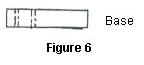
Two double LEDs with green upper and red lower lights. One double LED with green upper and yellow lower lights. This comprised a set for one switch. From Digi-Key Corporation, P.O. Box 677, Thief River Falls, MN 56701-0677 each LED Part Nos. 350-1396 or 1397-ND cost $1.53. (Figure 1)
- Two resistors for each double LED were required at a cost of 11 cents each from the same source. My power source for LEDs is 3 volts DC. Since many LEDs need around 2 volts DC, resistors are normally required to reduce the voltage for each LED. I therefore needed 100 ohm ¼ watt resistors for each green/red LED and 90 ohm ¼ watt resistors for each green/yellow LED. So that meant that I had a whopping $1.75 invested for each Dwarf Signal.
- Thin plastic sheet material about .01 inches thick. I used a portion of a plastic "FOR SALE" sign.
- A sheet of heavy aluminum foil. An odd scrap piece will probably do.
- CA (cyanoacrylate) adhesive with a mid-to-slow cure (20 - 90 seconds).
- A piece of plastic or wood 10 x 5 x 2 mm for each Dwarf Signal. You may find a piece of plastic spruce with the appropriate dimensions, as I did.
- Paint --- Cement and silver, gray or black.
Tools I Used
- Small ruler in millimeters.
- Sharp X-acto knife and/or single edge razor blade in a holder.
- Paper punch that cut a hole approximately 6 mm in diameter.
- Small scrap of blue board or foam plastic. Mine is 1 x 3 x ¾ inches.
- Small paint brush(es).
- Pin vice with drill bits.
- Awl or punch with a point that is not super sharp.
- Small file or emery board.
- Round toothpick.
- Tweezers.
- Soldering iron or gun and solder.
How I Created the Dwarf Signals
- Cut a 4 x 10 mm piece of plastic for the back end of each double LED body or case.
- Using CA adhesive, glue the plastic just cut in Step 1 to the back of each LED body. Use the piece of blueboard to hold the LED during the glue drying by sticking the LED pins into it.
- Once the glue is set (I wait until the next day or spray it with ZIP KICKER by Pacer), file the edges even with the LED body.
- Cut four 7 x 3 ½ mm plastic pieces for the sides of each LED body, two 3 ½ x 3 mm plastic pieces for the back and one 7 x 3 mm piece for the top of each LED body. Then decide which side of the seven little pieces is to be the front and back. Place them on your work surface BACK side up.
- Make a dimple by each corner of each of the 7 pieces using the awl or punch. When you turn a piece over to look at the front side, it should appear as if there is a bolt in each corner. If they are not exact in placement or the awl or punch has penetrated through the plastic, do not worry. Most likely it will never be noticed after it is painted.
- Add the 7 plastic pieces with the dimples to a double LED body as follows:
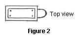
- Top of LED Body. Spread CA adhesive on body top and place the plastic piece cut for the top on the adhesive - bottom side down against the adhesive - centering the plastic piece on the top so that there is a small amount of the LED body showing along each edge of the plastic piece just added. (Figure 2)
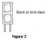
- Back or End of LED Body. Spread CA adhesive on the body back and place the 2 plastic pieces cut for the back on the adhesive - bottom side down against the adhesive - centering the two pieces so that there is a space between them as well as a small amount of the LED showing along the edges of the pieces just added. (Figure 3)
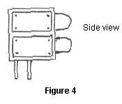
- Side of LED Body. Each side of the LED body is done in a similar manner as the end. Spread CA adhesive along one side of the body. Select 2 of the 4 plastic pieces cut for the sides and place the backs of them on the adhesive - bottom side down, long way from front to back, against the adhesive - centering the 2 pieces so that there is a space between them as well as a small amount of the LED showing along the edges of the pieces just added. Now do the other side in similar fashion. (Figure 4)
- After all of the pieces are dry on the LED body, paint the entire Dwarf Signal except the bottom, 4 wire pins and the LED light bulbs that protrude from the body face or front. It may require more than one coat of paint and/or some touch-up.
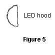
- Next take a piece of aluminum foil about 6 x 8 inches and fold it over on its self several times so that there are multiple layers of foil. You may need to experiment a bit for the optimum number of foil layers to punch out your 6 mm diameter circles and there may be some minor trimming along the edges of the foil circles. Separate the foil circles so there is only one layer per circle. Cut each circle in half with that sharp knife or razor blade. Each circle half will be used as the hood over the portion of an LED that protrudes from the body. (Figure 5)
- Using a round toothpick carefully roll it over one of the circle halves so the tips begin to curl slightly. Spread some CA adhesive along the top and sides of a protruding LED bulb. Using tweezers place a circle half on the top of the protruding LED with the CA adhesive. The straight side of the circle half should be against the LED body. Carefully push the points of the circle half down against each side of the bulb. Check to be sure that each side is pretty even. Your toothpick may be very handy for adjusting the Dwarf Signal hood.
- After the hoods are set, you may wish to paint them like the body.
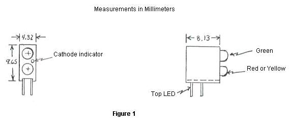
- From the old flat spruce or piece of wood, cut the base. Drill 4 holes through the base for the LED leads. Remember that the leads must protrude through the base. (Figure 6)
- Paint the base as cement. Glue the base to the LED body once the paint is dry using CA adhesive.
- Each LED has 2 pins for the electrical hook-up - one is the anode (positive) and the other is the cathode (negative). If you happen to get your wires reversed, there will be no light and probably no damage to your LED. Solder a 100 ohm resistor to each anode on a green/red signal or a 90 ohm resistor to each anode on a green/yellow signal. The 2 cathode pins on the signal should have a single wire soldered to them. But which is which is which you ask? When you face the front of the LED bulbs, the cathode pins are on the right - which is noted, by the way, on the front of the LED body with a very small circular indent between the 2 bulbs on the right. It shows in the catalog diagram of the LED along with all of its key measurements.